Thank you everyone who attended my session at both DevConf Cape Town and Johannesburg I met so many awesome people during DevConf inside and outside of my session! Thank you for making DevConf 2024 the incredibile conference it was!
I’ve included the slides for those interested in building your own DIY Microscope, or something similar to help you with your own accessibility challenges. If you have an imaging device with some intelligence, there’s so many things you can do!
The project is using a Raspberry Pi 3B (4 and 5 works too). It is build using C# and .NET 8. The user interface is created using AvaloniaUI. There’s nothing better that Avalonia if you need to create small, incredibly fast user interfaces on Linux using .NET. I really recommend trying it out!
The backend is using Azure CosmosDB for storage. The MongoDB VCore Implementation. This is chosen for it’s vector search capabilities. Perfect for a conversational solution using OpenAI.
The whole premise of the talk was to inspire developers to think about using all these tech components in your toolbox. Both AI and IoT bits and use it for good. There’s so many solutions that could be created especially for accessibility, to make people’s life a little easier. This is also exactly why I created this Microscope, to solve my own accessibility problems when building IoT solutions. Think about what you could do!
It’s time to start moving the indoor IoT Farm to being an outdoor IoT farm. The idea I have is to do some experimentation and research into creating automated constrained space farms. I’m going to turn this into a hands on hack series for the CPTMSDUG user group and also share the learnings. Hopefully it goes well. 😁
Today was the big shopping day to get everything I need.
Shopping at the nursery with the much needed coffee.
Some nice wooden planters from the Pole Yard.
Preparing the soil
The offerzen Basil that was grown at a hack event was planted
Getting there
The first evening of the indoor crop being outdoors
I hope you enjoyed the Microsoft Developer Cloud Summit today! Thank you very much for attending my session: Automating your home or office with IoT Central and Power Apps” It was a lot of information in 30 min, so here’s the content, resources and source code.
This whole session was done using Home Automation devices combined with OBS. Camera Scene changes were controlled with a standard home remote control. So automation doesn’t have to be traditional garage doors or lighting, you can control you PC life too! 😎 Controlling your OBS Scenes with a Home Automation device
I came across this Smart Watering Kit by Elecrow. It was really great, but one thing missing is internet conectivity. We all know that we can’t grow plants without the “I” in IoT! So let’s see what we can do about that!
Electrow Ardunio Smart Plant Watering KitInside the box
The kit comes with everything you need to water four different plants automatically.
The box contains
Arduino Leonardo
Power Supply
Pump
4 Capacitive Moisture Sensors
4 Way valves
Pipes
The kit is very comprensive and includes and LCD display which can show at a glance the conditions of your plants.
The boardSerial Port
The board unfortunately does not have built in wifi connectivity. But what it does have is a serial port. That’s perfect, so what we could do is use that to send telemetry out to another device that is internet / wifi enabled.
A good device for that is a good old (and cheap) 8266 board. I had a NodeMCU in my box of tricks, so I decided to use that.
Parts List
Arduino Smart Watering Board (Arduino Leonardo)
NodeMCU board
2.2 K ohm resistor
1 K ohm Resistor
470 ohm Resistor
Breadboard
Wires
Power Supply
Connecting an Arduino Leonardo to a Node MCU via Serial Port
First step is to make it work on a breadboard.
Parts List
Arduino Smart Watering Board (Arduino Leonardo)
NodeMCU board
2.2 K ohm resistor
1 K ohm Resistor
470 ohm Resistor
Veroboard
Wires
Power Supply
Connecting an Arduino Leonardo to a Node MCU via Serial Port
Once working, the next step is to build that onto a more permanent solution. I decided to use just veroboard as it was quick and easy.
Two boards up and running
IoT Central
Device Templates
Device Capabilities
Create device capabilities for the moisture sensors as telemetry (Moisture1, Moisture2, Moisture3, Moisture4). [Device Definition json file is in the github repository along with the source code]
Create properties for the 4 relay states for each of the 4 valves. [Device Definition json file is in the github repository along with the source code]
Create a property for the pump state. [Device Definition json file is in the github repository along with the source code]
Publish the template and create an instance of the template as a device.
Instance of a device template
Note the “connection” information for the new device instance.
Device “Connection” information
Take note of the following:
Scope ID
Device ID
Primary Key
iotcserialrelay.ino
Update the iotcserialrelay.ino file with the:
WIFI_SSID – The wifi hotspot ssid
WIFI_PASSWORD – The wifi hotspot password
SCOPE_ID – The Device Instance’s Scope Id
DEVICE_ID – The Device Instance’s Device Id
DEVICE_KEY 0 The Device Instance’s Key
Deploy iotcserialrelay.ino to NodeMCU.
Deploy watering_kit.ino to the Arduio Smart Watering Board.
Telemetry in IoT Central
Once deployed and connection is made, telemetry starts appearing within IoT Central’s dashboard.
Finished Product with happy plants powered by Microsoft Azure 😎😎
You can easily set up a standard 433 Mhz remote control that you use every day in your home to control scenes in OBS (Open Broadcast Software) if you don’t own a fancy Stream Deck.
All you need is a remote, a 433 Mhz Wifi Bridge and some Node-RED magic.
Node-RED Switch using button codes to control flow
The 433 Mhz Bridge when it detects a signal, it publishes a message with it’s contents via MQTT. These will have codes attached to them and in the case of a remote, that code / data that is sent via the message payload translates to the button pressed. You can “train” your solution with the remotes you have. These can be standard house-hold remotes.
Scene flows per button press
The switch statements routes the flow based on the button data to a specific function.
Scene switch command to OBS Socket Server
The function sends a message with the “scene-name” with the parameter of the scene created in OBS.
Scenes in OBS
For additional commands refer to the protocol document:
Device Definition json file is in the github repository along with the source code. This can be imported into Azure IoT Central and the views generated.
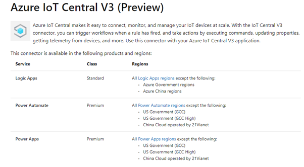
Azure IoT Central makes it easy to connect, monitor, and manage your IoT devices at scale. With the IoT Central V3 connector, you can trigger workflows when a rule has fired, and take actions by executing commands, updating properties, getting telemetry from devices, and more. Use this connector with your Azure IoT Central V3 application.
Due to the dynamic nature of Azure IoT Central, using the connector is not quite straight-forward. To use the Azure IoT Central connector in Canvas apps you need to enable two features in the settings of the application.
These are:
Enhanced formula bar
Dynamic Schema
Enabling these two features allows Power Apps to understand the resulting schema from a call to IoT central. “Capture Schema” will be enabled on the formula bar.
Power Apps Canvas Settings: Enhanced Formula BarPower Apps Canvas Settings: Dynamic SchemaFormula bar: Schema Capture
Power Automate
Power Automate is a lot simpler to get to work. It automatically understand the dynamic schemas of IoT Central.
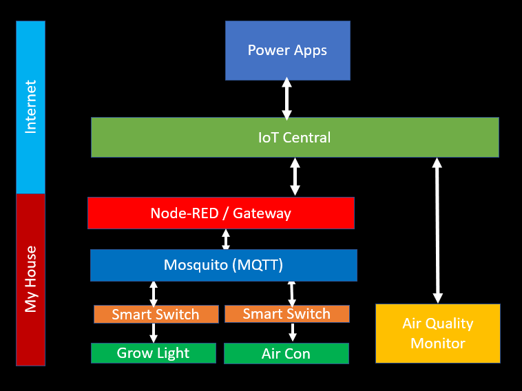
I control a few devices from the Internet, but I don’t want all devices exposed and connected to IoT Central. One solution is to build a gateway locally which routes request messages to switch things on or off to the correct device locally.
In this post we will look at how to send commands from IoT Central and route them using Node-RED to the automation device via MQTT.
Home Automation Gateway Architecture
This architure uses Node-RED as a gateway, and then uses Eclipse Mosquito as a MQTT server. The Grow Light and Air Conditioner in the diagram is an off the shelf Sonoff POW-R2 device flashed with Tasmota.
With Node-RED you can visually map the flow / sequence of events. Node-RED supports Azure IoT Hubs and Azure IoT Central, so it’s perfect for this job to do quickly and easily without having to write code.
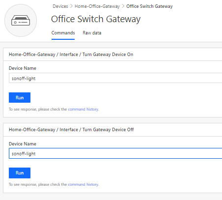
Gateway device created in IoT Central’s Command Capabilities
In Azure IoT Central we have a single device linked with a command. The command accepts a parameter, which will be the device name / topic name on the local MQTT server.
Executing a command on IoT Central
The diagram above shows the command with the parameter.
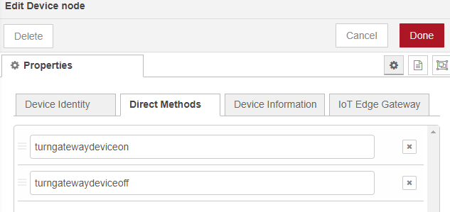
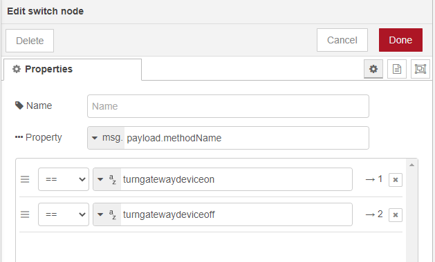
Defined Methods to IoT Central Commands
The Node-RED Azure component supports Direct Methods. These are commands that you can directly invoke on a device. In this case, the device is the gateway itself created within Node-RED.
It supports two methods (as per Azure IoT Central template)
turngatewaydeviceon
turngatewaydeviceoff
Switch to determine flow based on Direct Method Invoked from IoT Central
With a Node-Red switch statement we can controll the flow with whichever method name was invoked from IoT Central.
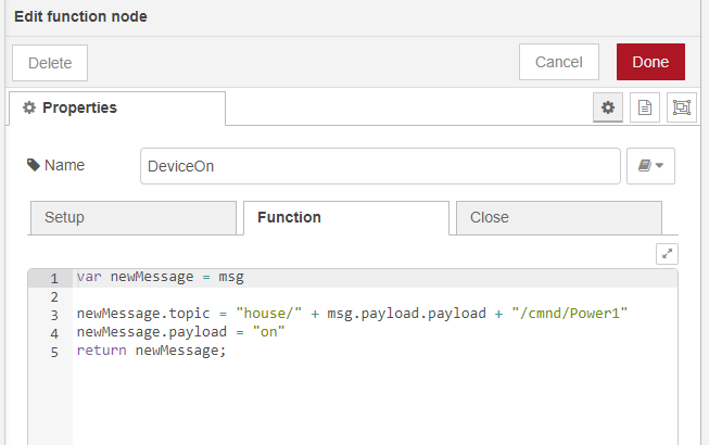
Switch Home Automation On flow
If it’s the “DeviceOn” flow, then the device parameter name (payload) is used to build up the topic for the Sonoff device via MQTT. The payload of the message will be “on”.
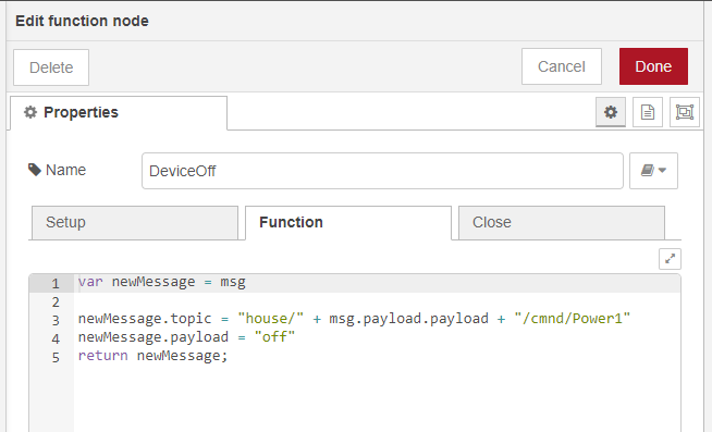
Switch Home Automation Device Off Flow
If it’s the “DeviceOff” flow, then the device parameter name (payload) is used to build up the topic for the Sonoff device via MQTT. The payload of the message will be “off”.
The Sonoff devices are great, but I prefer to use everything within my home and home automation setup to be fully under my control. Tasmota is a great way of doing just that.
I found the easiest way of flashing devices with Tasmota is using a raspberry pi. I’ve done a quick writeup on how to do this.
Choose Interfacing OptionsConfigure SerialDisable login shell via serialEnable serial port hardwareSerial setup complete
Connect the Raspberry Pi to the Sonoff Device
Raspberry Pi Pinouts (Serial)
The TXD (Transmit) and RXD (Receive) pins are marked on the raspberry pi. We can use these to communicate serially with the Sonoff Device to flash it with the Tasmota firmware.
Sonoff POW R2 Device
Each Sonoff device has pins allocated to reflash the device. These boards usually don’t have headers attached. Here I soldered one to the board.
The important pins are VDD, TX, RX and GND.
Flashing the device with a Raspberry Pi
Connect VDD to an external power supply. The Raspberry Pi will not be able to power the device off it’s own pins. I used an external bench power supply. Ensure the voltage is 3.3V.
Connect the GND on the power supply to both the Raspberry Pi Ground Pins and the Sonoff device’s GND pin
Connect the TXD on the Raspberry Pi to the RX Sonoff pin and connect the RXD on the Raspberry Pi to the TX Sonoff pin.