Building an Azure IoT Central “Gateway” using Node-RED

I control a few devices from the Internet, but I don’t want all devices exposed and connected to IoT Central. One solution is to build a gateway locally which routes request messages to switch things on or off to the correct device locally.

In this post we will look at how to send commands from IoT Central and route them using Node-RED to the automation device via MQTT.

Home Automation Gateway Architecture

This architure uses Node-RED as a gateway, and then uses Eclipse Mosquito as a MQTT server. The Grow Light and Air Conditioner in the diagram is an off the shelf Sonoff POW-R2 device flashed with Tasmota.

Flashing with Tasmota

Installing Eclipse Mosquitto in a Container

Installing Node-RED in a Container
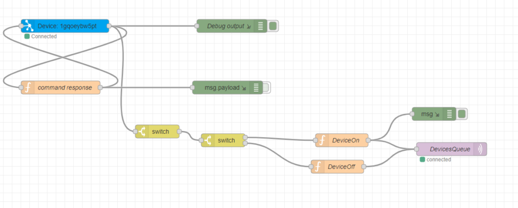
“Gateway” flow in Node-RED

With Node-RED you can visually map the flow / sequence of events. Node-RED supports Azure IoT Hubs and Azure IoT Central, so it’s perfect for this job to do quickly and easily without having to write code.

Gateway device created in IoT Central’s Command Capabilities

In Azure IoT Central we have a single device linked with a command. The command accepts a parameter, which will be the device name / topic name on the local MQTT server.

Executing a command on IoT Central

The diagram above shows the command with the parameter.
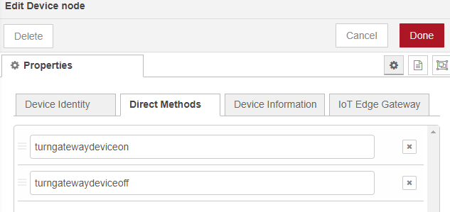
Defined Methods to IoT Central Commands

The Node-RED Azure component supports Direct Methods. These are commands that you can directly invoke on a device. In this case, the device is the gateway itself created within Node-RED.

It supports two methods (as per Azure IoT Central template)

  • turngatewaydeviceon
  • turngatewaydeviceoff
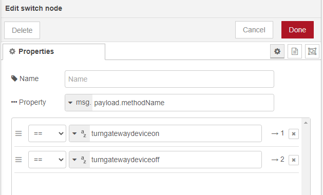
Switch to determine flow based on Direct Method Invoked from IoT Central

With a Node-Red switch statement we can controll the flow with whichever method name was invoked from IoT Central.
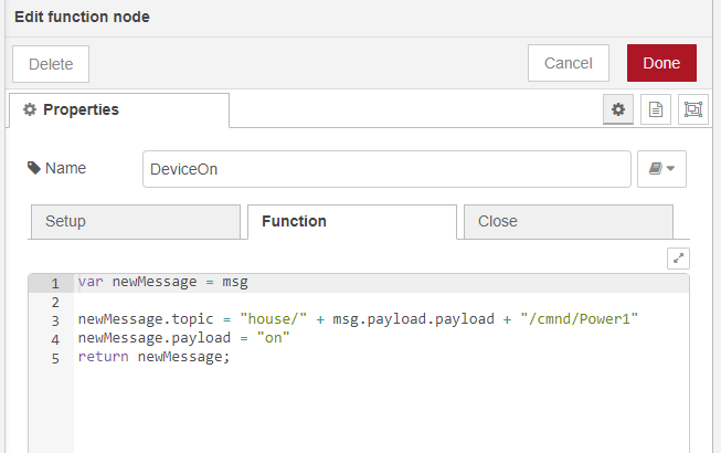
Switch Home Automation On flow

If it’s the “DeviceOn” flow, then the device parameter name (payload) is used to build up the topic for the Sonoff device via MQTT. The payload of the message will be “on”.
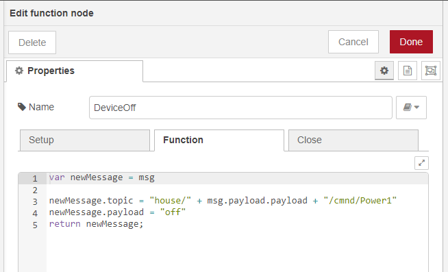
Switch Home Automation Device Off Flow

If it’s the “DeviceOff” flow, then the device parameter name (payload) is used to build up the topic for the Sonoff device via MQTT. The payload of the message will be “off”.

Flashing Sonoff Devices with TASMOTA

The Sonoff devices are great, but I prefer to use everything within my home and home automation setup to be fully under my control. Tasmota is a great way of doing just that.

I found the easiest way of flashing devices with Tasmota is using a raspberry pi. I’ve done a quick writeup on how to do this.

Installing ESPTool

Start with installing via the installer script

pip install esptool

Clone from the GitHub repository

git clone https://github.com/espressif/esptool.git

Preparing the Raspberry Pi

sudo raspi-config
Choose Interfacing Options
Configure Serial
Disable login shell via serial
Enable serial port hardware
Serial setup complete

Connect the Raspberry Pi to the Sonoff Device

Raspberry Pi Pinouts (Serial)

The TXD (Transmit) and RXD (Receive) pins are marked on the raspberry pi. We can use these to communicate serially with the Sonoff Device to flash it with the Tasmota firmware.

Sonoff POW R2 Device

Each Sonoff device has pins allocated to reflash the device. These boards usually don’t have headers attached. Here I soldered one to the board.

The important pins are VDD, TX, RX and GND.

Flashing the device with a Raspberry Pi

Connect VDD to an external power supply. The Raspberry Pi will not be able to power the device off it’s own pins. I used an external bench power supply. Ensure the voltage is 3.3V.

Connect the GND on the power supply to both the Raspberry Pi Ground Pins and the Sonoff device’s GND pin

Connect the TXD on the Raspberry Pi to the RX Sonoff pin and connect the RXD on the Raspberry Pi to the TX Sonoff pin.

Download the Tasmota Firmware

curl http://ota.tasmota.com/tasmota/ --output tasmota.bin

This terminal command will download the latest firmware from the Tasmota site to the Raspberry Pi.

sudo ./esptool.py --port /dev/ttyS0 erase_flash

Start by erasing the devices Flash memory

The port to use on a Raspberry Pi 3 or 4 is /dev/ttyS0.

sudo ./esptool.py --port /dev/ttyS0 write_flash -fm dout 0x0 tasmota.bin

Flash the device with the dowloaded firmware.

Once flashed, reassemble the device and power it on. It should appear as an access point on the network as Tasmota-xxxx if all went well.

You can also follow the Tasmota getting started guide to continue the setup: https://tasmota.github.io/docs/Getting-Started/