It’s now been many months of eating some really good and fresh produce. I’m going to declare the IoT exeperient and learning a success. Next step is to package it into a Sustainable Hack Series that anyone can build.


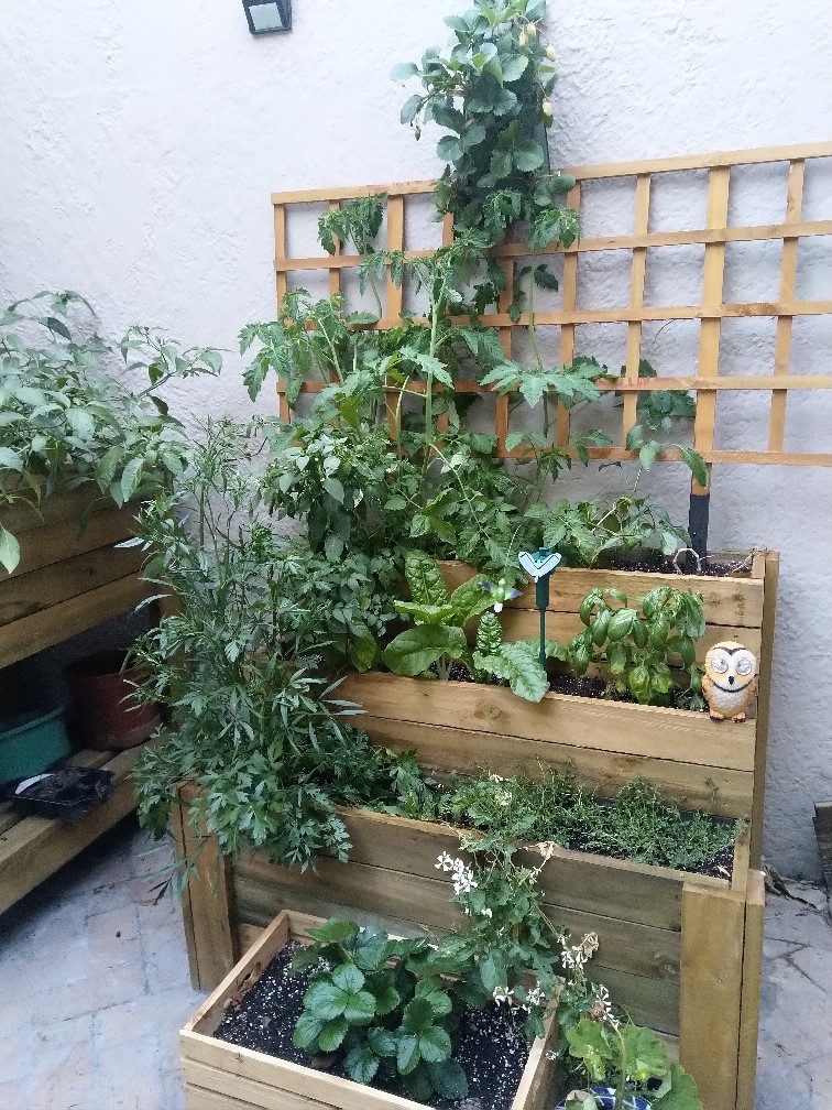


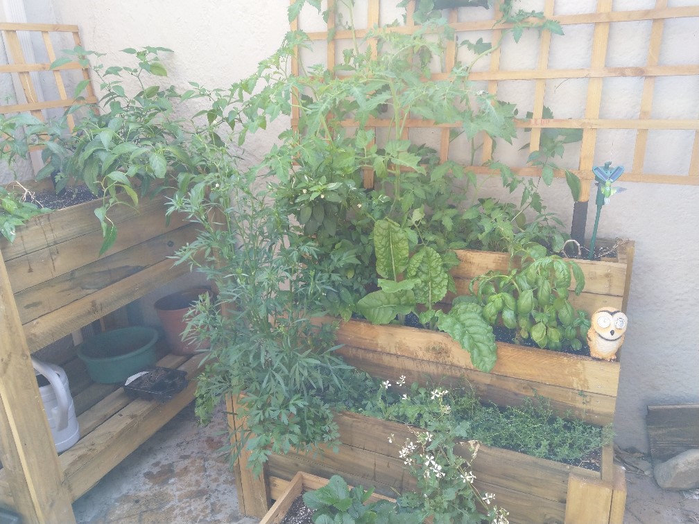


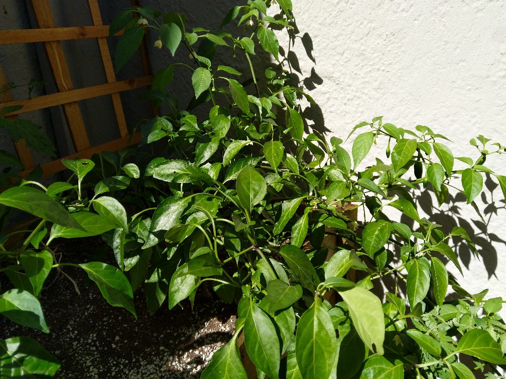


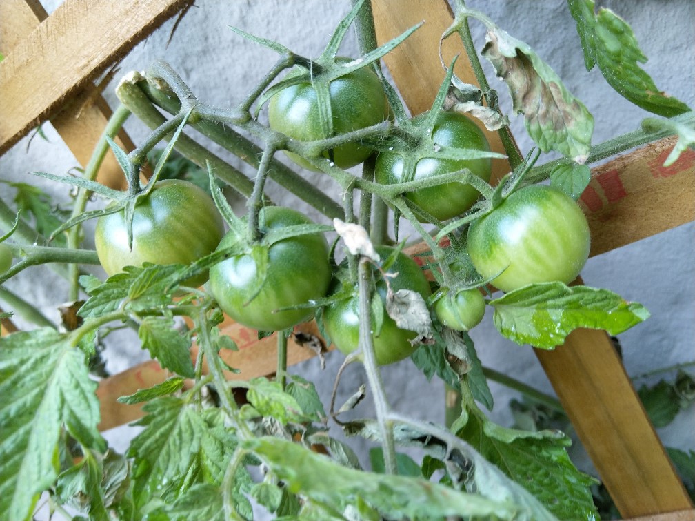


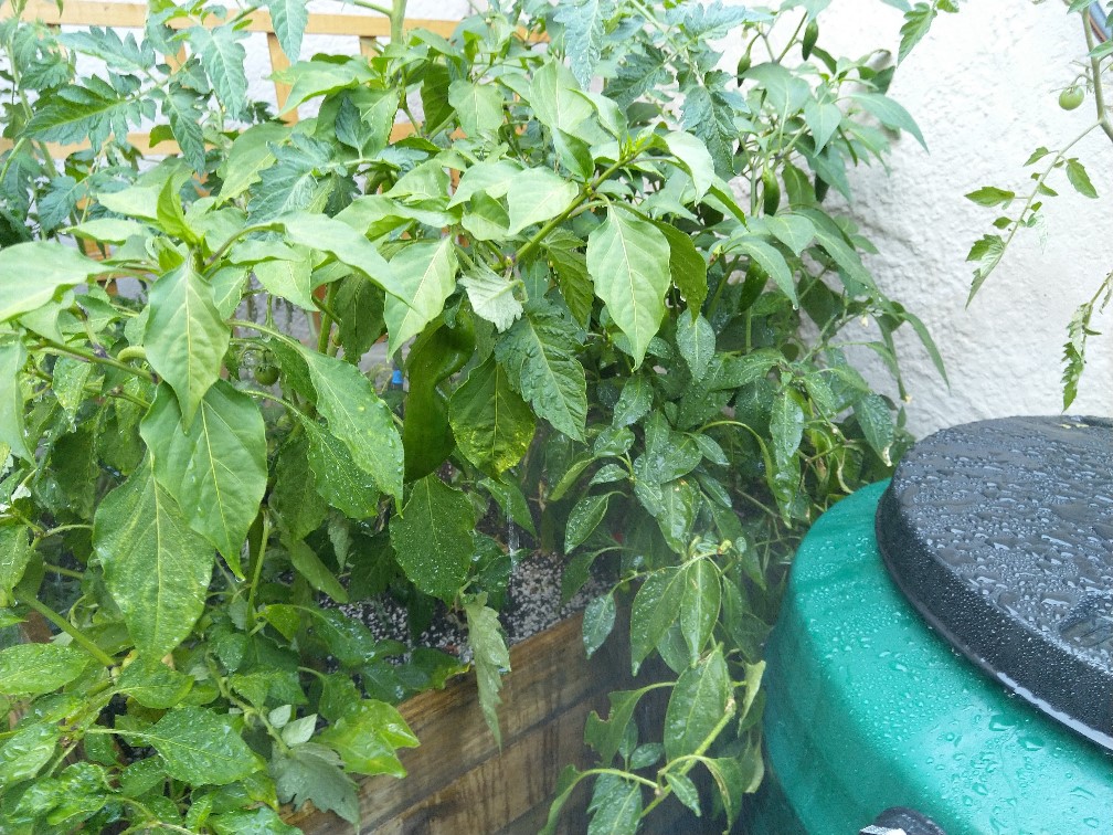


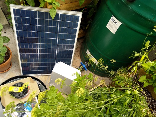
For this outdoor farm to be truely sustainable I decided to water it with rain water tanks and have it self powered by the sun with solar panels.


It’s time to start moving the indoor IoT Farm to being an outdoor IoT farm. The idea I have is to do some experimentation and research into creating automated constrained space farms. I’m going to turn this into a hands on hack series for the CPTMSDUG user group and also share the learnings. Hopefully it goes well. 😁
Today was the big shopping day to get everything I need.


Thanks DUT for an amazing Embeded Conference!
The source code can be found here for the Arduino AZ3166 waterer: https://github.com/apead/az3166arduinogrower
As promised here is the content shared.
Happy gardening!

Woohoo!! So excited my Azure Percept arrived. Time to do some playing. 😊
Learning Resources
Azure Percept DK and Vision device overview https://docs.microsoft.com/en-us/azure/azure-percept/overview-azure-percept-dk
Azure Percept sample AI models https://docs.microsoft.com/en-us/azure/azure-percept/overview-ai-models
AI @ the Edge https://www.youtube.com/channel/UCa8_TsUuotIMuzkLzGNQPIg
Azure Percept Audio Overview- set up and use your voice assistant https://www.youtube.com/watch?v=K9HfwsDGVnU
Azure Percept | Build & Deploy to edge AI devices in minutes https://www.youtube.com/watch?v=zSBNsEqU5NA
Azure Percept showing Edge Computing and AI in the Agriculture https://youtu.be/1H-U8psvxYE


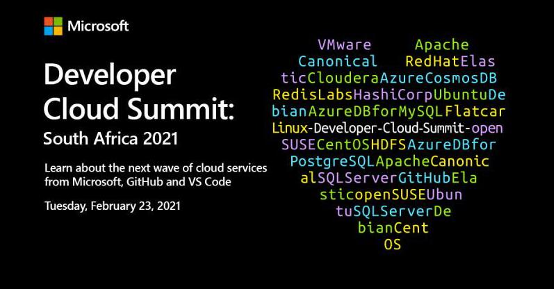
I hope you enjoyed the Microsoft Developer Cloud Summit today! Thank you very much for attending my session: Automating your home or office with IoT Central and Power Apps” It was a lot of information in 30 min, so here’s the content, resources and source code.
This whole session was done using Home Automation devices combined with OBS. Camera Scene changes were controlled with a standard home remote control. So automation doesn’t have to be traditional garage doors or lighting, you can control you PC life too! 😎 Controlling your OBS Scenes with a Home Automation device
Link to Presentation: Microsoft Developer Cloud Summit 2021 Presentation
Connecting a Pimoroni Environment Monitor to IoT Central
Connecting Azure IoT Central to Power Apps and Power Automate
Arduino Smart Watering Kit with Azure IoT Central
Building an Azure IoT Central “Gateway” using Node-RED
Flashing Sonoff Devices with TASMOTA
Controlling your OBS Scenes with a Home Automation device
Installing Node-RED in a Container
Installing Eclipse Mosquitto in a Container
IoT Central
https://azure.microsoft.com/en-us/services/iot-central/
Power Apps
https://powerapps.microsoft.com/en-us/
Node-RED
Tasmota
https://tasmota.github.io/docs/
Environmental Monitor
https://www.pishop.co.za/store/enviro–for-raspberry-pi?keyword=enviro&category_id=0
Sonoff
I came across this Smart Watering Kit by Elecrow. It was really great, but one thing missing is internet conectivity. We all know that we can’t grow plants without the “I” in IoT! So let’s see what we can do about that!


The kit comes with everything you need to water four different plants automatically.
The box contains
The kit is very comprensive and includes and LCD display which can show at a glance the conditions of your plants.


The board unfortunately does not have built in wifi connectivity. But what it does have is a serial port. That’s perfect, so what we could do is use that to send telemetry out to another device that is internet / wifi enabled.
A good device for that is a good old (and cheap) 8266 board. I had a NodeMCU in my box of tricks, so I decided to use that.
Parts List

First step is to make it work on a breadboard.
Parts List

Once working, the next step is to build that onto a more permanent solution. I decided to use just veroboard as it was quick and easy.

Device Templates

Create device capabilities for the moisture sensors as telemetry (Moisture1, Moisture2, Moisture3, Moisture4). [Device Definition json file is in the github repository along with the source code]
Create properties for the 4 relay states for each of the 4 valves. [Device Definition json file is in the github repository along with the source code]
Create a property for the pump state. [Device Definition json file is in the github repository along with the source code]
Publish the template and create an instance of the template as a device.

Note the “connection” information for the new device instance.

Take note of the following:

Update the iotcserialrelay.ino file with the:
Deploy iotcserialrelay.ino to NodeMCU.
Deploy watering_kit.ino to the Arduio Smart Watering Board.

Once deployed and connection is made, telemetry starts appearing within IoT Central’s dashboard.

Source code: https://github.com/apead/SmartWateringKit
Product Information: https://www.elecrow.com/arduino-automatic-smart-plant-watering-kit.html
Where to buy? https://www.robotics.org.za/AAK90039K
You can easily set up a standard 433 Mhz remote control that you use every day in your home to control scenes in OBS (Open Broadcast Software) if you don’t own a fancy Stream Deck.
All you need is a remote, a 433 Mhz Wifi Bridge and some Node-RED magic.

Flash the bridge using these instructions: https://explorationspace.co.za/2021/02/10/sonoff-rf-bridge-433-tasmota/


Install the OBS Websocket plugin: https://github.com/Palakis/obs-websocket/releases/tag/4.9.0

The 433 Mhz Bridge when it detects a signal, it publishes a message with it’s contents via MQTT. These will have codes attached to them and in the case of a remote, that code / data that is sent via the message payload translates to the button pressed. You can “train” your solution with the remotes you have. These can be standard house-hold remotes.

The switch statements routes the flow based on the button data to a specific function.

The function sends a message with the “scene-name” with the parameter of the scene created in OBS.

For additional commands refer to the protocol document:
https://github.com/Palakis/obs-websocket/blob/4.x-current/docs/generated/protocol.md
Happy streaming! 😎
Sonoff RF Bridges are great to take every day houshold remotes, alarm systems, passive IR seasons etc , and pass the codes they transmit via MQTT messages.
These bridges can also be flashed with the Tasmota open-source firmware used for Home Automation.


Follow the instructues in this post to flash with the Tasmota Firmware (using the TX, RX, VDD, GND configuration pins) above: https://explorationspace.co.za/2020/12/10/flashing-sonoff-devices-with-tasmota/
The Pimoroni Environmental monitor is an amazing piece of hardware. I recently purchased a few to monitor air quality around the house. https://shop.pimoroni.com/products/enviro?variant=31155658457171

Packed into the HAT for a Raspberry Pi Zero you will find:

Device Definition json file is in the github repository along with the source code. This can be imported into Azure IoT Central and the views generated.


Source code: https://github.com/apead/Pimoroni-Env-Monitor-IoT-Central
Product Information: https://shop.pimoroni.com/products/enviro?variant=31155658457171
Where to buy?